

Industrial Battery Management Systems (BMS) For LiFePO4 And Energy Storage
Category Overview
Modern lithium iron phosphate (LiFePO4) energy storage systems and low/high-voltage battery packs require hardware-enforced protection, active cell balancing, and deterministic telemetry. A Battery Management System (BMS) serves as the primary node protecting battery infrastructure against overvoltage, undervoltage, overcurrent, and thermal runaway.
For B2B procurement engineers, system integrators, and pack assemblers, selecting an industrial-grade BMS dictates field reliability, warranty liability, and grid-compliance. This catalog outlines scalable BMS architectures engineered for low-voltage residential packs, high-voltage commercial string systems, rack-mounted modular banks, and multi-megawatt C&I containers. Built on dual-MCU safety architectures, isolated communication channels, and configurable hardware protection layers, these units meet rigorous industrial standards for stationary and mobile applications.


BMS Product Range
Our manufacturing output spans six core BMS categories tailored to specific voltage tiers, topology requirements, and energy capacities:
48V LiFePO4 Battery Management System
Architecture: 15S to 16S configuration.
Target Application: Standard telecommunication backup, residential low-voltage storage, and light e-mobility packs.
Key Distinction: Integrated hardware short-circuit protection and passive balancing currents up to 200mA.
51.2V LiFePO4 Battery Management System
Architecture: 16S LiFePO4 specific topology with nominal operating voltage at 51.2V.
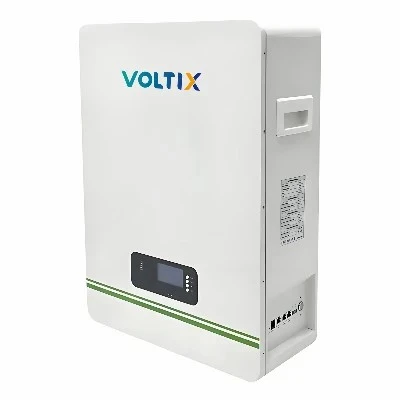
Target Application: 5kWh to 15kWh residential wall-mount and stackable energy storage modules.
Key Distinction: Multi-protocol inverter handshaking (CAN/RS485) pre-flashed for leading hybrid inverter brands.
Low-Voltage ESS Battery Management System
Architecture: Configurable from 8S to 24S (Nominal < 60VDC).
Target Application: Off-grid power systems, marine auxiliary banks, and RV/fleet energy storage.
Key Distinction: Conformal-coated PCB assemblies for high-humidity and marine-grade salt fog resistance.
High-Voltage ESS Battery Management System
Architecture: Master-Slave distributed topology supporting 80S to 250S+ (200VDC to 1000VDC+).
Target Application: Commercial energy storage cabinets, utility-scale solar farms, and high-power EV charging buffers.
Key Distinction: High-precision optical isolation, dedicated HV interlock loops, and active balancing capabilities.
Rack Battery Management System
Architecture: Standard 19-inch 2U/3U subrack integration for 48V or high-voltage modular racks.
Target Application: Data center backup power rooms, modular server rack storage, and scalable containerized energy blocks.
Key Distinction: Front-access wiring terminals, hot-pluggable internal harness connectors, and LED fault matrix indicators.
C&I Battery Management System
Architecture: Scalable cluster controller architecture managing parallel string arrangements up to MWh levels.
Target Application: Commercial peak shaving, industrial microgrids, and factory energy management reserves.
Key Distinction: Multi-channel temperature tracking (up to 32 NTC sensors per cluster) and redundant safety cut-off contactor control.
Industrial battery operation depends on deterministic, real-time control algorithms executed continuously at the firmware level:
State of Charge (SoC) and State of Health (SoH) Estimation:Employs a hybrid algorithm combining Coulomb counting with Open Circuit Voltage (OCV) correction and extended Kalman filtering (EKF) to maintain SoC estimation error within +/-3 percent, even under fluctuating thermal and load conditions.
Cell Voltage and Temperature Monitoring: Independent analog front-end (AFE) ICs sample individual cell voltages at 10ms intervals. Multiple negative temperature coefficient (NTC) thermistors positioned across critical hotspots track thermal gradients in real time.
Active and Passive Cell Balancing:
Passive Balancing: Bleed resistors dissipate excess energy from fully charged cells during the constant-voltage charge phase.
Active Balancing: Energy-shuttling topology transfers charge between high-capacity and low-capacity cells, minimizing thermal loss and maximizing usable pack energy.
Fault Detection and Protection Interlocks: Triggers immediate hardware disconnection upon detecting overvoltage, undervoltage, charge/discharge overcurrent, extreme temperatures, or communication timeouts. Independent hardware secondary protection fuses act as a fail-safe against primary MOSFET/contactor failure.

Key Specifications
|
Technical Parameter |
Low-Voltage Series (48V / 51.2V / LV ESS) |
High-Voltage and C&I Series (HV / Rack / C&I) |
|
Cell Series Count (S) |
8S to 24S |
80S to 280S (Master-Slave Architecture) |
|
Operating Voltage Range |
20VDC to 60VDC |
200VDC to 1000VDC |
|
Continuous Operating Current |
100A / 150A / 200A (Customizable) |
Up to 300A per string (Contactor-dependent) |
|
SoC Accuracy |
+/- 3 percent |
+/- 2 percent |
|
Voltage Sampling Accuracy |
+/- 5mV |
+/- 2mV |
|
Temperature Sensors |
4 to 8 NTC Probes |
16 to 64 NTC Probes per cluster |
|
Balancing Current |
50mA to 200mA (Passive) / 1A to 5A (Active opt.) |
200mA (Passive) / 2A to 10A (Active) |
|
Operating Temperature |
-20°C to +70°C |
-30°C to +75°C |
|
Storage Temperature |
-40°C to +85°C |
-40°C to +85°C |
|
PCB Conformal Coating |
Dual-side military-grade acrylic/silicone |
Dual-side UV-cured acrylic coating |
System integration requires standardized, reliable physical layers and communication protocols to interface with inverters, PLCs, and cloud energy management systems (EMS):
Physical Interfaces:
Dual CAN 2.0B ports, RS485 interfaces, and isolated RS232 maintenance ports.
Protocol Support:
Pre-integrated communication libraries for major hybrid and off-grid inverter manufacturers (e.g., Victron, GoodWe, Growatt, Deye, SMA, and custom MODBUS RTU/TCP protocols).
Daisy-Chain Topology:
Master-Slave architecture enables simple multi-rack expansion without requiring external hub hardware. Cluster controllers aggregate data and communicate upstream via industrial Ethernet (Modbus TCP / SNMP).
Diagnostic Tools:
PC-based diagnostic software and mobile terminal apps provide real-time graphing of cell voltages, cycle logs, fault history registers, and firmware update flashing over serial interfaces.
Battery Compatibility
While optimized for Lithium Iron Phosphate (LiFePO4 / LFP) chemistry, firmware parameters can be re-configured for alternative chemistries:
Primary Chemistry:
LiFePO4 (LiFePO4) - optimized for 3.2V nominal, 3.65V max charge, and 2.5V cut-off thresholds.
Alternative Chemistries:
Configurable discharge cut-off, charge voltage ceilings, and temperature protection limits for Lithium Nickel Manganese Cobalt (NMC) and Lithium Titanate (LTO).
Cell Format Agnostic:
Compatible with prismatic cells, pouch cells, and cylindrical cells (e.g., 26650, 32145, 38125) via customizable busbar wire harnesses and balancing connector pinouts.
BMS reliability is governed by strict manufacturing controls and environmental validation protocols executed in our 20,000+ square meter production facility:
Production Equipment: Automated pick-and-place (SMT) lines, automated optical inspection (AOI), selective wave soldering, laser welding equipment for shunt resistors, and automated functional test (ICT/FCT) rigs.
Environmental Stress Screening (ESS): Production batches undergo thermal cycling in high/low-temperature test chambers (-40°C to +85°C) and vibration table testing to detect cold solder joints or component drift prior to shipment.
Electrical Verification: 100 percent board-level testing of isolation withstand voltage (Dielectric strength testing up to 2500VDC), power MOSFET on-resistance verification, and current shunt calibration.
Traceability: Every BMS unit is laser-marked with a unique 2D barcode linked to component lot numbers, test logs, and calibration profiles stored in our quality management database.
Compliance Standards: Manufacturing processes comply with ISO9001 and ISO14001 frameworks. Finished hardware complies with CE, RoHS, UN38.3 transport requirements, and relevant clauses of IEC62133 safety standards.
Customization
Standard off-the-shelf units often fail to meet exact enclosure constraints, port layouts, or proprietary inverter protocols. We provide comprehensive OEM/ODM customization services:
Hardware Modification: Redesigning PCB dimensions, modifying connector pinouts (Amphenol, Anderson, Molex), adjusting continuous current ratings, or integrating specialized high-voltage contactors.
Firmware Development: Custom CAN-bus protocol implementation for proprietary inverters, tailored state-of-charge calculation curves for specific cell chemistries, and unique fault-handling logic.
Mechanical Engineering: Custom aluminum enclosure extrusion, IP67 waterproof potting options, and bespoke mounting bracket configurations.
Engineering Engagement Workflow:
Technical requirement review and electrical load profile analysis.
Schematic and PCB layout generation (Prototypes delivered within 3 to 4 weeks).
Hardware-in-the-loop (HIL) testing and customer sample sign-off.
Pilot run batch production and full-scale manufacturing rollout.
FAQ

RFQ
To evaluate our BMS solutions for your upcoming project, please provide the following technical parameters to our engineering sales team:
System Voltage and Configuration: Nominal system voltage and cell series count (e.g., 16S 51.2V, 96S 384V).
Current Requirements: Continuous operating discharge current and peak surge current requirements.
Application Type: Residential storage, commercial container, telecommunication backup, or e-mobility.
Inverter / System Protocol: Target inverter brand and required communication protocol (CAN 2.0B, Modbus RTU, etc.).
Project Timeline and Volume: Estimated annual procurement volume and prototype delivery schedule.
Submit your technical specifications or request an engineering consultation via our direct contact channel to receive a comprehensive proposal and quotation within 24 business hours.
We're well-known as one of the leading battery management systems (bms) manufacturers and suppliers in China. With abundant experience, we warmly welcome you to wholesale high quality battery management systems (bms) made in China here from our factory. Contact us for more details.