

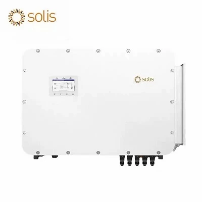
Product Overview
The High-Voltage Energy Storage System (ESS) Battery Management System (BMS) is engineered for commercial, industrial, and utility-scale lithium-ion battery clusters. Operating across voltage ranges from 150V to 1500V DC, this master-slave architecture monitors, protects, and regulates multi-string battery stacks. It manages high-voltage DC switching, active pre-charging, thermal thresholds, and real-time state estimation, serving as the central control unit between battery racks and Power Conversion Systems (PCS).
Key Specifications
|
Parameter |
Specification Details |
|
Operating Voltage Range |
150V DC to 1000V DC (Standard) / up to 1500V DC (Extended) |
|
Supported Cell Chemistries |
LiFePO4, NMC, LTO (Lithium Titanate) |
|
Master-Slave Capacity |
Supports up to 16 slave monitoring units per master controller |
|
Current Measurement Accuracy |
+/- 0.5% FSR (Full Scale Range) via high-precision shunt resistors or Hall-effect sensors |
|
Cell Voltage Sampling Accuracy |
+/- 2mV (0°C to 60°C) |
|
Communication Interfaces |
CAN 2.0B, RS485, Modbus TCP/IP, Ethernet |
|
Isolation / Insulation Monitoring |
Built-in insulation resistance detection (>500 kohm threshold) |
|
Operating Temperature |
-20°C to +65°C |
|
Ingress Protection |
IP20 (Rack / Cabinet Integration) |
|
Certifications |
UL 1973 Recognized, CE, IEC 60730-1, UN 38.3 (Cell/Module Level) |
Key Product Characteristics
Active Cell Balancing: Utilizes bi-directional active balancing currents up to 2A per channel to equalize state-of-charge (SoC) across mismatched series cells during charge and discharge cycles.
Controlled Pre-Charge Circuitry: Integrated 30A pre-charge contactors and thermal-rated power resistors eliminate high inrush currents, preventing DC bus capacitor damage and contactor welding upon startup.
Real-Time Insulation Monitoring: Continuously measures isolation resistance between high-voltage DC paths and chassis ground, triggering instantaneous faults if dielectric breakdown occurs.
Redundant Thermal Management: Interfaces with external liquid-cooling plates or forced-air HVAC units via PWM and dry-contact outputs, enforcing dynamic current derating when cell temperatures exceed safe operating boundaries.
Hardware Architecture & System Topology
The modular hardware topology consists of three primary functional blocks:
Master Control Unit (BMU / Control Box): Houses the main MCU, dual-core processors, high-voltage relays, 150A+ DC contactors, insulation detection module, and primary communication ports (CAN/RS485).
Cell Supervisory Units (CSU / Slave Boards): Directly mounted onto battery module terminals to collect individual cell voltages (up to 36 cells per board) and NTC thermistor temperatures via wire harnesses.
Stack Switchgear / PDU: Manages busbar connection, short-circuit fuses, and main breaker tripping mechanisms.
Applications
Commercial & Industrial (C&I) Microgrids: 100kW to 2MW behind-the-meter energy storage installations for peak shaving and demand charge management.
Utility-Scale Solar + Storage Farms: Megawatt-hour (MWh) battery energy storage systems (BESS) coupled directly with central inverters operating at 1000V+ DC.
Telecom Backup Power Stations: High-reliability 400V DC remote telecom container power systems requiring zero downtime.
EV Fleet Charging Hub Buffers: High-power stationary storage banks absorbing grid fluctuations during rapid electric vehicle charging sessions.
Compatibility & Integration
Inverter Protocols: Native communication library pre-integrated with major PCS and inverter manufacturers (including Sungrow, SMA, Schneider Electric, and GoodWe) via custom CANopen and Modbus mapping.
EMS Integration: Open API and register maps allow seamless handshake with third-party Energy Management Systems (EMS) and supervisory SCADA platforms.
Physical Mounting: Standard 19-inch rack-mountable enclosures and standalone wall-mounted control boxes designed for integration into standard NEMA / IP54 outdoor battery cabinets.
Supply & Customization Options
Firmware Customization: Tailored state-of-charge (SoC) and state-of-health (SoH) algorithms calibrated against specific cell manufacturer discharge curves.
Hardware Adaptation: Custom wire harness lengths, auxiliary digital/analog I/O expansion ports, and alternative busbar terminal orientations.
Minimum Order Quantity (MOQ): Evaluation kits available for 1 master + 4 slaves; volume production MOQs start at 50 units.
Lead Time: Standard configurations ship within 4 weeks; custom firmware integration requires 6 to 8 weeks.
Quality / Testing
End-of-Line (EOL) Testing: 100% automated optical inspection (AOI) of PCB assemblies, dielectric withstand voltage testing (hipot testing at 2500V AC for 60 seconds), and calibration verification for current/voltage sensors.
Environmental Stress Screening (ESS): Thermal cycling chamber testing (-40°C to +85°C operating simulation) and 48-hour full-load burn-in testing prior to dispatch.
Traceability: Component-level barcode scanning tracks individual semiconductor lots, relay batches, and sensor calibration certificates.
FAQ
Q: Does this BMS support parallel rack aggregation without external hardware?
A: For multi-rack parallel configurations (up to 16 racks), an additional Multi-Stack Controller (MSC) is required to aggregate CAN bus lines and present a unified interface to the PCS.
Q: What happens if communication between the master unit and slave boards fails?
A: The system enforces a failsafe shutdown procedure, opening the main DC contactors within 20 milliseconds to isolate the battery stack.
Q: Are raw communication protocols open for custom software integration?
A: Yes, complete Modbus register maps, CAN message definitions, and DBC files are provided under NDA to system integrators.
Hot Tags: high-voltage ess battery management system, China high-voltage ess battery management system manufacturers, suppliers, factory