

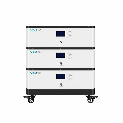
Product Overview
This low-voltage energy storage system (ESS) battery management system (BMS) monitors and protects 48V/51.2V LiFePO4 battery packs used in residential and commercial stationary storage. The hardware architecture tracks individual cell voltages, module temperatures, and bidirectional current flows to prevent overcharge, deep discharge, short circuits, and thermal runaway. Engineering integration relies on standard CAN 2.0B / RS485 communication protocols for direct inverter handshaking and state-of-charge (SoC) calibration.
Key Specifications
|
Parameter |
Specification |
|
Nominal System Voltage |
48V / 51.2V (15S / 16S LiFePO4 configuration) |
|
Operating Voltage Range |
40VDC to 58.4VDC |
|
Continuous Discharge Current |
Up to 100A / 150A (configurable via software) |
|
Communication Interfaces |
CAN 2.0B, RS485, RS232 |
|
Voltage Measurement Accuracy |
plus-minus 5mV (at 25 deg C) |
|
Temperature Sensors |
4 to 6 NTC probes per pack (Cells & MOS terminals) |
|
Balancing Method |
Passive balancing (current: 50mA to 100mA) |
|
Operating Temperature |
-20 deg C to +65 deg C |
|
Ingress Protection |
PCB conformal coating against humidity and salt mist |
|
Certifications |
ISO9001 factory standard compliance, CE, RoHS, UN38.3 (system level) |
Key Product Characteristics
Dual-Core MCU Architecture: Utilizes isolated processing units for real-time fault detection and communication, ensuring safety instructions execute independently of host inverter polling.
Hardware-Level Short-Circuit Protection: Hardware fuse and secondary MOSFET trip circuits react within microseconds during output faults, bypassing software latency.
Dynamic SoC/SoH Estimation: Combines Coulomb counting with open-circuit voltage (OCV) calibration algorithms to maintain state-of-charge error margins below plus-minus 3 percent.
Thermal Management Integration: Triggers cooling fans or heating films dynamically based on multi-point NTC thermistor inputs, preventing lithium plating at sub-zero temperatures.
Passive Cell Balancing: Automatically dissipates energy from higher-voltage cells during the charging phase to equalize pack capacity and extend service life.
Hardware & Software Architecture
Topology: Master BMS board paired with slave acquisition boards (supports parallel clustering up to 16 packs).
Main Control Unit (MCU): Industrial-grade ARM Cortex processor with watchdog timers.
Switching Elements: High-current low-on-resistance Power MOSFETs or magnetic latching relays.
Wiring & Harnesses: Flame-retardant UL94-V0 rated connectors, integrated data ribbon cables, and ring terminals for busbar attachment.
Software Toolchain: PC-side debugging and configuration tool for reading historical fault logs, setting thresholds, and executing firmware updates.
Applications
Residential Energy Storage: Pairs with 48V household hybrid inverters and wall-mounted / rack-mounted LiFePO4 battery modules.
Commercial & Industrial (C&I) Microgrids: Scalable multi-rack configurations for peak shaving and load shifting.
Telecom Base Station Backup: Provides reliable 48V DC bus stability for remote or off-grid cellular infrastructure.
Low-Speed E-Mobility & Industrial AGVs: Overcurrent and vibration-resistant power monitoring for heavy-duty electric transport.
Compatibility & Integration
Inverter Protocols: Pre-integrated communication libraries for major global inverter brands (e.g., Victron, GoodWe, Deye, Pylontech protocol standards).
Physical Mounting: Compact PCB dimensions tailored for standard 19-inch rack enclosures and custom prismatic cell module layouts.
Parallel Expansion: Supports DIP-switch or software-addressed master-slave stacking for multi-module bank expansions up to 800Ah total capacity.
Supply & Customization Options
Manufacturing Scale: Backed by 20,000+ square meters production facilities featuring automated SMT lines and dedicated BMS debugging stations.
Hardware Customization: Tailored PCB dimensions, custom connector pinouts, alternative current sensor ratings (Hall-effect or shunt resistors), and specific relay configurations.
Firmware Adaptation: Customized communication baud rates, proprietary CAN protocol mapping for non-standard inverters, and custom fault trip thresholds.
Minimum Order Quantity (MOQ): Flexible batch policies for pilot testing and full-scale commercial deployment.
Quality / Testing
Production Line Testing: 100 percent automated optical inspection (AOI), in-circuit testing (ICT), and functional burn-in testing under simulated load conditions.
Environmental Stress: Thermal chamber cycling (-20 deg C to +70 deg C) and vibration testing to verify solder joint integrity.
Traceability: Individual serial barcode scanning logs production timestamps, component lot numbers, and calibration parameters for every unit.
FAQ
Q: Can this BMS support parallel connection of multiple battery packs?
A: Yes. Up to 16 identical 48V packs can be connected in parallel using master-slave architecture via CAN bus communication.
Q: How does the BMS handle communication errors with the inverter?
A: If CAN/RS485 communication drops, the BMS falls back to pre-configured voltage and temperature protection thresholds to maintain safe operation independently.
Q: Is it possible to modify current limit thresholds for specific cell chemistries?
A: Yes. Overcharge, discharge cut-offs, and temperature trip points are fully configurable using the supplied PC debugging software interface.
Q: What lead time is required for custom protocol integration?
A: Standard firmware adaptations typically require 1 to 2 weeks for engineering validation and sample delivery.
Hot Tags: low-voltage ess battery management system, China low-voltage ess battery management system manufacturers, suppliers, factory