

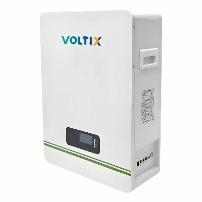
Product Overview
The Rack Battery Management System (BMS) is engineered for 48V/51.2V lithium iron phosphate (LiFePO4) server rack energy storage configurations. It monitors cell-level parameters, enforces thermal protection thresholds, and balances cell voltages across 15 to 16 series-connected prismatic cells. Built to fit standard 19-inch server racks, the system acts as the central safety and telemetry controller for telecommunications backup power, data center uninterruptible power supplies (UPS), and commercial renewable energy storage arrays.
Key Specifications
|
Parameter |
Technical Specification |
|
Nominal System Voltage |
48V / 51.2V DC (15S / 16S configuration) |
|
Supported Cell Chemistry |
Lithium Iron Phosphate (LiFePO4) |
|
Continuous Operating Current |
100A / 200A (configurable via firmware) |
|
Voltage Measurement Accuracy |
+/- 5 mV per cell channel |
|
Temperature Sensors |
4 to 6 NTC thermistors (internal board & cell terminals) |
|
Communication Interfaces |
CAN 2.0B, RS485, RS232, SNMP (optional) |
|
Operating Temperature Range |
Charging: 0 deg C to 55 deg C; Discharging: -20 deg C to 65 deg C |
|
Ingress Protection (IP) Rating |
IP20 (Enclosed rack chassis required for outdoor deployment) |
|
Safety Compliance |
CE, RoHS, UN38.3, IEC62133 aligned firmware and hardware architecture |
Key Product Characteristics
Real-Time Cell Telemetry: Continuously tracks individual cell voltages, pack current, and ambient/internal temperatures to prevent localized thermal runaway.
Passive Cell Balancing: Utilizes automated resistor-based bleed balancing during the charging cycle to equalize cell capacities and mitigate voltage drift.
Hardware-Level Layered Protection: Features redundant semiconductor cut-off switches independent of software loops, isolating the DC bus instantly upon detecting short-circuits or voltage spikes.
Open Protocol Integration: Supports multi-brand inverter handshake protocols (including Victron, Pylontech, GoodWe, and Growatt) via standard CAN/RS485 physical layers.
Modular Scalability: Accommodates parallel stacking of up to 16 rack units without requiring external master controller hardware.
Hardware Architecture & Internal Modules
Master Control Board: Houses the primary MCU, communication transceivers (CAN/RS485), and non-volatile memory for black-box fault logging.
Slave Acquisition Boards: Distributed PCB assemblies mounted directly on cell modules to capture high-density voltage and temperature data, routing via isolated internal bus lines.
Current Shunt / Hall Sensor: High-precision current measurement hardware providing Coulomb counting for accurate State of Charge (SoC) and State of Health (SoH) estimation.
Power Switching Circuitry: Opto-isolated MOSFET or contactor driver circuits controlling main power path interruption.
Physical Enclosure: UL94-V0 flame-retardant structural housing with integrated copper busbar mounting interfaces.
Applications
Telecom Base Stations: Ensures continuous DC power delivery for remote cellular towers during municipal grid outages.
Data Center Sub-Racks: Provides localized backup support for server racks and network switches within tight spatial footprints.
Commercial Solar-Plus-Storage: Manages peak shaving and load shifting in industrial microgrids paired with hybrid string inverters.
Off-Grid Industrial Cabins: Stabilizes intermittent renewable inputs for remote monitoring stations and oil/gas telemetry units.
Compatibility & Integration
Inverter Communication: Pre-programmed with multi-inverter communication libraries; verifies voltage windows and current limits before closing main contactors.
Busbar and Cabling: Accepts standard M8 terminal bolted lugs and modular plug-and-play communication patch cables (RJ45 pinouts for CAN/RS485).
Monitoring Software: Interfaces with PC service tools via RS232 for parameter tuning, firmware flashing, and historical log extraction.
Supply & Customization Options
Firmware Customization: Tailored over-voltage, under-voltage, and temperature cut-off thresholds adjusted to specific cell manufacturer data sheets.
Communication Protocols: Custom CANopen or Modbus register mapping adjustments for proprietary industrial SCADA integration.
OEM/ODM Enclosure Branding: Silk-screened front panels, custom terminal layouts, and specialized wiring harness lengths available for volume orders.
Quality / Testing
Automated Board Inspection: Printed Circuit Board Assemblies (PCBAs) undergo automated optical inspection (AOI) and X-ray inspection for solder joint integrity.
Functional End-of-Line Testing: Every BMS unit undergoes automated test equipment (ATE) validation, verifying current shunt accuracy, isolation resistance (> 20 Mohm at 500V DC), and communication handshake response.
Thermal Stress Screening: Hardware samples undergo accelerated aging and burn-in testing under elevated temperature chambers to weed out infant mortality component failures.
FAQ
Q: Can this BMS manage 15S and 16S battery configurations simultaneously?
A: No. Hardware channel assignments and firmware voltage thresholds must be factory-set or re-flashed specifically for either a 15S (LiFePO4) or 16S (LiFePO4) topology.
Q: How does the system handle communication loss with the inverter?
A: If the CAN/RS485 heartbeat signal from the inverter drops beyond a pre-set timeout window (default 30 seconds), the BMS defaults to safe autonomous operation mode, restricting charge/discharge based on locally measured cell limits.
Q: Is external power required to boot up the BMS during initial installation?
A: The BMS derives its operating power directly from the connected battery pack once cell voltage exceeds the minimum sleep threshold (typically > 35V for a 48V system). A manual wake-up switch or pre-charge circuit is integrated.
Hot Tags: rack battery management system, China rack battery management system manufacturers, suppliers, factory